
17 Feb Dissimilar Material and/or Hardness as a Function of Gear Size, Application
Poor performance in terms of the application of material properties and/or heat treatment can make a good theoretical gear design provide unsatisfactory service.
Some say that metallurgy is a ‘black art’. Actually, it is a very skilled art, demanding in its precision and consistency. The people who practice metallurgy and tribology are very skilled in these arts, techniques, and technologies. The appropriate selection and specification of material for a gear pair design, coupled with the precise implementation of the requirements of heat treatment to optimize material performance, as we all know, can make a gear design perform admirably. Just as easily, poor performance in terms of the application of material properties and / or heat treatment can make a good theoretical gear design provide very unsatisfactory service.
As we have learned from our studies and through implementation of the various calculations and design techniques, materials play an integral role in gear design, specifically in expected or predicted service life, either through high cycle fatigue as in surface compressive stress or tooth root failure. Certainly, there are considerations regarding the environment, specifically as resistance to corrosion, magnetic fields interference, food, and medical environments. Some materials are even used to dampen or attenuate NVH issues as a function of their properties and / or internal structure.
There are many considerations when selecting a material for a gear pair. As we all know the design of a gear set is influenced by the application and even more by the anticipated failure mechanism; long life versus catastrophic tooth bending. The presence or absence of shock loading, temperature extremes and even external sources of vibration may add to the frequency response spectrum of the gear mesh and support bearing pass frequencies. Even more detailed considerations are required for the selection of two differing materials in a gear pair or, as a minimum, the difference in metallurgical properties of the same or similar materials in mesh.
This is a wide-ranging subject, and the expanse is beyond the room we have here. The concentration will therefore be on the subset of the topic; material dissimilarities within the contact patch. As well, an in-depth discussion of microstructure is beyond the scope of this article. It is worth mentioning that the degree of martensitic structure is one of the prime indicators of a material’s quality. AGMA 2004- B892 does a good job of identifying other microstructural aspects that must be considered.
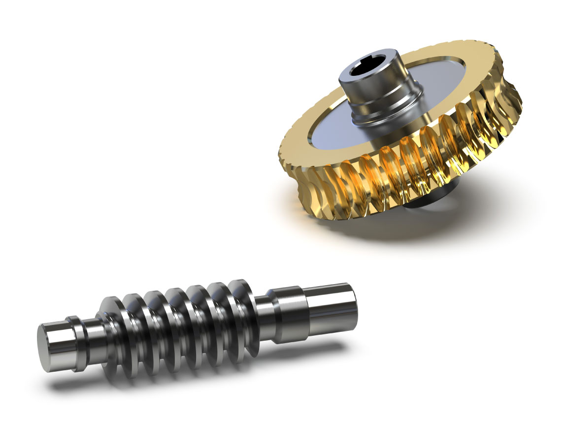
Base material properties are also considered in wear rates. As the most obvious example, balancing wear of a worm relative to the wheel it runs with is the analytic mechanism used to determine the service life of a worm and wheel gearset. Generally speaking, the material of the wheel is selected to provide good performance in terms of sliding by either providing self-lubrication or, as a minimum, enhancing the function of the elastohydrodynamic shear layer in the lubricant between the two gear surfaces.
The specific effect of differences in material properties, specifically surface hardness, case depth, and microstructure are embedded in even the basic form of the Lewis equation. Two factors of interest are the Load Distribution Factor (Km and KH) and the Elastic Coefficient (Cp and ZE). The Load Distribution Factor is a mathematical means to describe the distribution of contact stress (applied load) across the surface of the gear tooth. The contact interface area (contact patch) is defined by the amount of local elastic deformation that occurs within the tooth surface and as a function of the induced stress by contact with the mating tooth. The local elastic deformation is basically a ratio of the flexibility of the surface of one tooth, within its elastic range, as a function of the interfacial geometry shared between the two teeth at the instantaneous point of contact and the load distributing effect of the elastohydrodynamic shear layer. This also has the effect of positioning the maximum sub-surface shear stress below the surface of the gear tooth. This effect is a combination of two factors, the thickness of the elastohydrodynamic shear layer causes the shear strain energy (induced by the sliding velocity and the resistance to shear in boundary layer lubrication) to induce a couple or moment at the surface of the gear tooth, which in turn causes the reaction (counter-couple) to reach maximum strain energy a non-negligible, measurable distance below the surface of the tooth. This separation of the position of maximum strain energy (e.g. compressive and shear) explains why the loaded tooth deflects locally just enough to stay below the yield limit of the material. The functional definition of yield limit in this case is the applied load that would cause the material to transition from its elastic range to its plastic range.
How do different materials and optimized heat treatment enhance this effect? By making the induced strain energy in both the driver and the driven tooth equal in both surface compressive and sub-surface shear stress. This is very theoretical and the actual calculations, etc., are beyond the scope of this article, but the procedure is well documented in the various standards and implemented in any number of analysis tools.
The other factor or effect, the Elastic Coefficient, ratios the induced strain energy into the surface of each gear (driver and driven) in a manner that compares by a simple weighting factor the differences in both Young’s modulus and Poisson’s ratio of the two materials. The AGMA development based on the Lewis equation calculates the effect of the differences in the material attributes (Young’s modulus and Poisson’s ratio) to attempt to evenly distribute the strain energy in both gear tooth surfaces. As designers, we can reverse the use intent and solve for desired strain energy distribution as a function of material properties, thus gear material, condition, quality, and heat treatment become a design variable. I encourage anyone interested in exploring this effect to take a fairly standard gear design and run through a small number of simulations by varying both material properties (different materials) and heat treat (basically surface hardness) for one of the two gears.
Another aspect of dissimilar material selection and heat treat specification is the ability to use these design variables in the prediction of high cycle fatigue. As discussed earlier, the difference in or balance of material properties as a function of high cycle fatigue is affected by the distribution of strain energy within the contact patch (2D surface) and sub-surface (depth of effect). As we know, work hardening is a function of both base material properties and the effect of surface heat treatment. For a high cycle gear design, the designer can use material dissimilarities as a means to predict localized work hardening. All these techniques are based on theory and although there is a great deal of empirical evidence to support these theories, as always, the best way to ensure your result is through testing.
Sorry, the comment form is closed at this time.